

|
|
 |
 |
 |

|
 |
BMW Garage | BMW Meets | Register | Search | Today's Posts | Mark Forums Read |
 |

|
BMW 3-Series (E90 E92) Forum
>
~DIY: $130 Rear View Camera with OEM integration (vendors will hate me)~
|
 |
| 03-08-2015, 09:35 AM | #243 |
|
Private First Class
 
20
Rep 188
Posts |
Excellent thanks for confirming. I've coded individual modules before but so far not added anything to my VO, the instructions look nice and straight forward so should be able to code this ok.
|
|
Appreciate
0
|
| 03-21-2015, 12:39 PM | #245 |
|
Private First Class
 
20
Rep 188
Posts |
You'd need to check with the seller as it might be different with the next gen wiring etc. There is a genuine OEM option of rear view camera on the F cars so performing this mod is definitely doable.
To anyone that has used the additional harness - how did you splice into the harness - is it just a case of stripping some insulation on the relevant wires, wrapping the stripped emulator wire around the harness wire and then soldering, and covering in insulation tape for example? Or have people used those clamp down wire splice things? Last edited by Scoff123; 03-21-2015 at 01:08 PM.. Reason: Found answer to other question |
|
Appreciate
0
|
| 03-22-2015, 10:14 AM | #246 |
|
Private First Class
 
20
Rep 188
Posts |
After taking delivery of the additional harness yesterday I set about starting this mod (at last!). I decided to splice into the harness by removing the relevant pins from the holders in the additional harness and soldering the emulator wires directly onto the pins to ensure a good connection and keep the harness as tidy as possible. I've taken some pictures which will hopefully help others going down the harness route. Some of it might be obvious but it might just help someone feel more confident to tackle this. I noticed that n8s 330xi had uploaded some additional harness pics which I didn't see the last time I read through the whole thread, so they helped
 but thought a few more pictures and details wouldn't do any harm and might help others who have little experience with wiring. but thought a few more pictures and details wouldn't do any harm and might help others who have little experience with wiring.Additional harness and emulator, with relevant harness wires separated from the rest  To attach the RCA socket to the new harness, remove the white clip by pressing down the tab on top and slide out the black insert from within the white plug in a similar way. Locate the pins that the RCA attaches to from the wiring diagram in this thread, remove the metal inserts from these pin numbers by depressing the small tag on top and then sliding them out, then replace these with the 2 pins on the end of the RCA plug 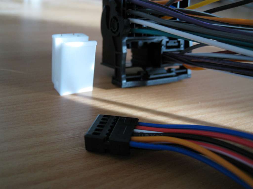 Pins removed 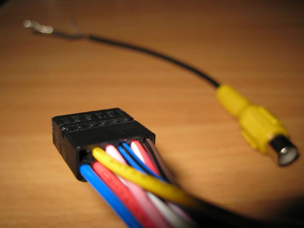 and replaced with RCA pins  Then pop the black plug back into the white larger plug, then put the white plug back into the quadlock connector 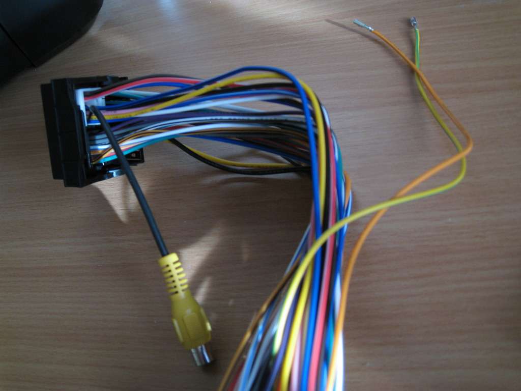 Then remove the unused wires that you have just replaced, from the other end of the harness in a similar fashion 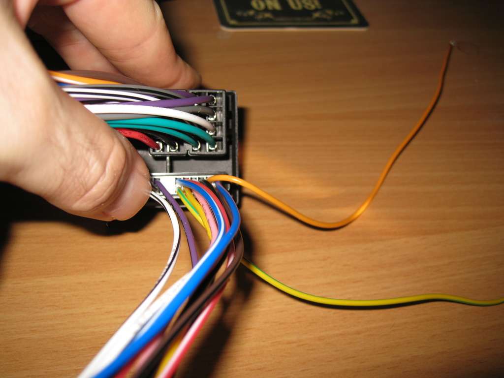 That's the RCA part done now 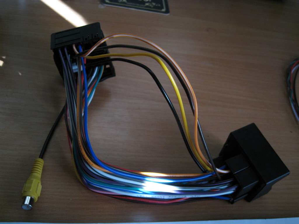 If you want to solder the emulator wires onto the relevant pins of the harness as I have, and at the same time twist the CAN wires as much as possible, first remove one of the CAN wire from the harness. These pins are held in the plastic housing by small barbs, one at either side of the pin (If you haven't dealt with these before  ) You can use a miniature screwdriver or a paper clip to slide down one side at a time and depress the barbs enough for the pin to slide out. Once removed, you can twist it around the other CAN wire most of the way along, leaving enough room to work with for soldering etc ) You can use a miniature screwdriver or a paper clip to slide down one side at a time and depress the barbs enough for the pin to slide out. Once removed, you can twist it around the other CAN wire most of the way along, leaving enough room to work with for soldering etc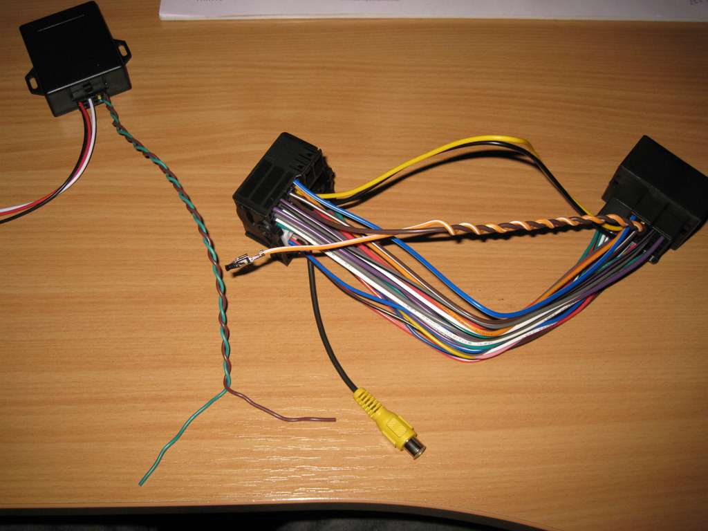 Sorry for the dark picture, but you can still see how I soldered the wires 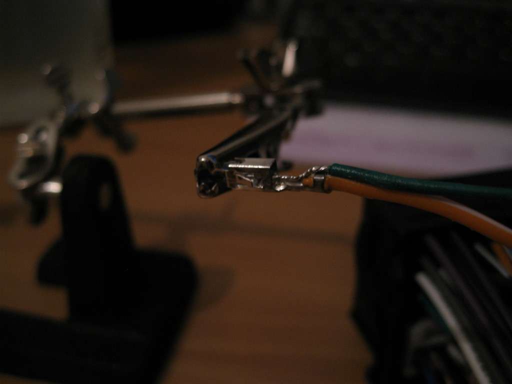 Then just a little bi of shrink sleeving for good measure (You can see one of the side barbs here in the picture what need to be pushed in to remove these type of pins from their housing. I gently prised them back out before fitting so they will spring open and hold the pins when it's back in it's housing) 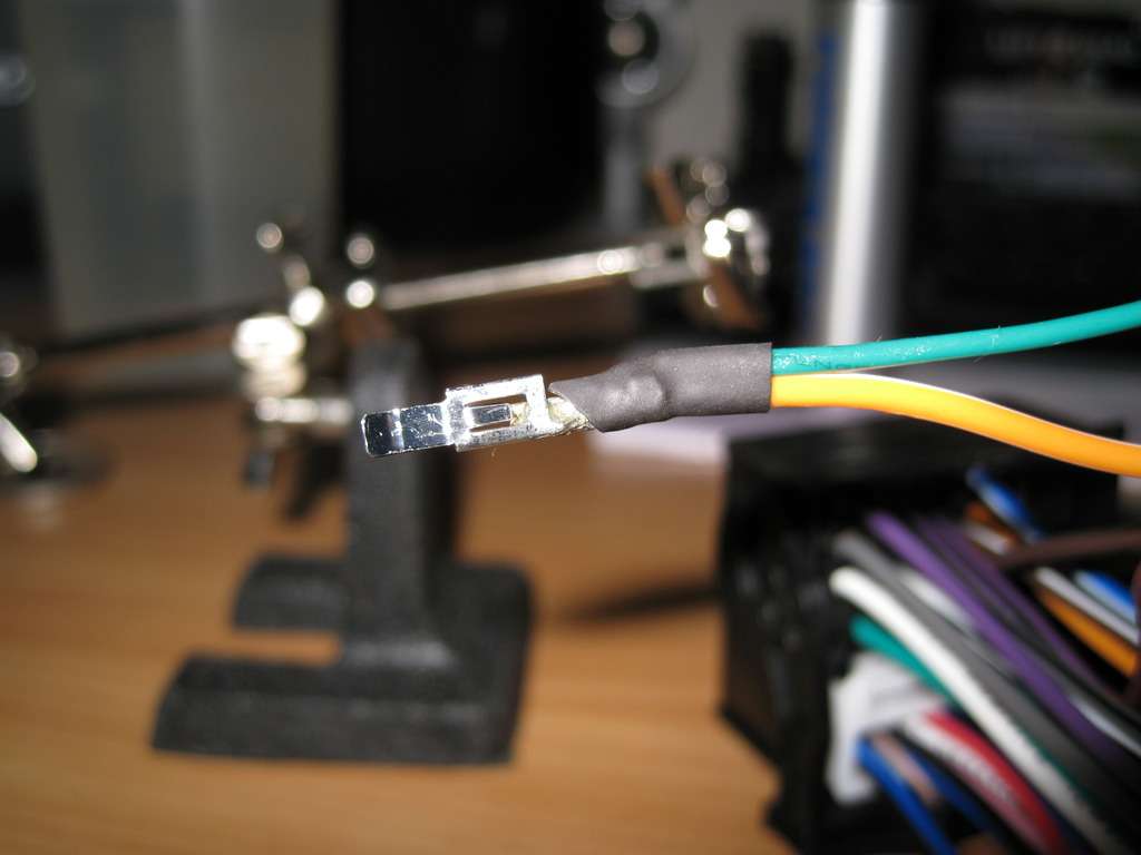 Both CAN wires done  And inserted back into the plug 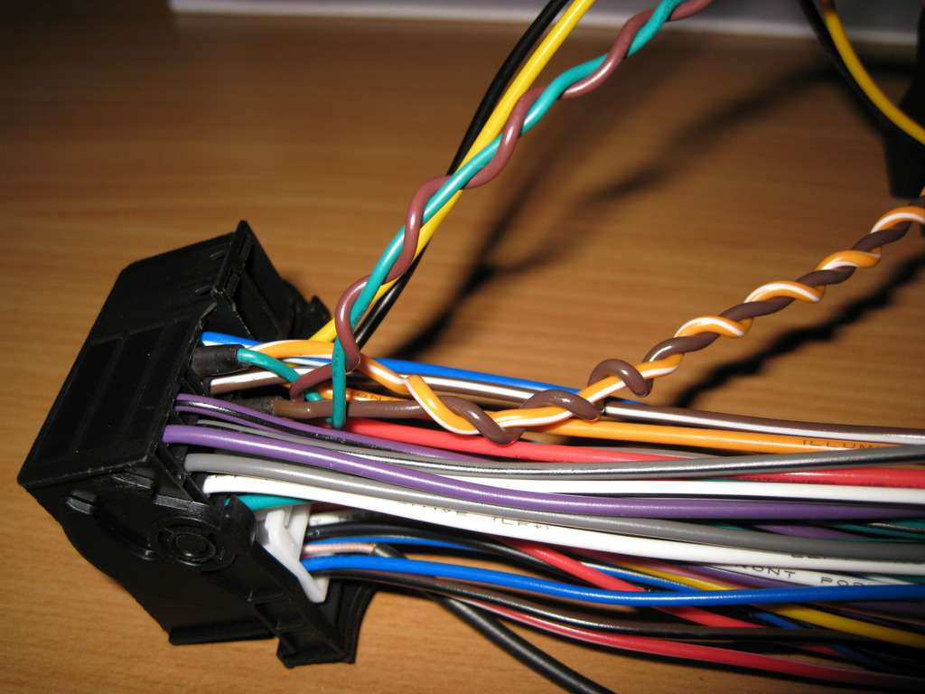 Just the red and black emulator wires to do now - these I done in exactly the same way 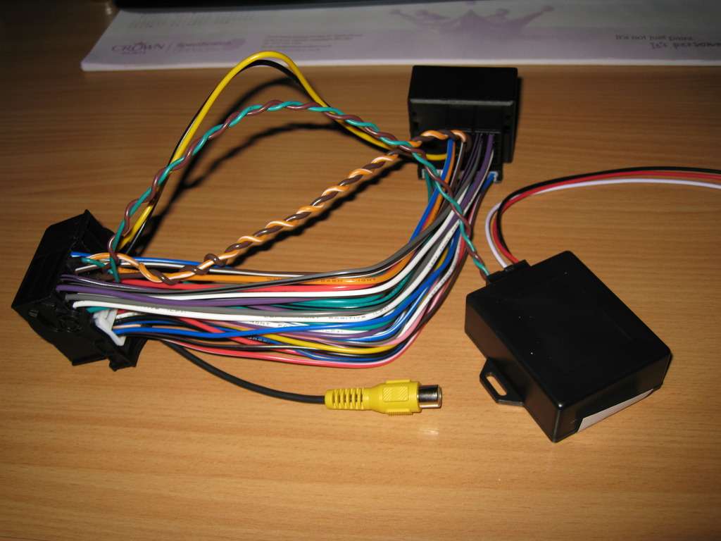 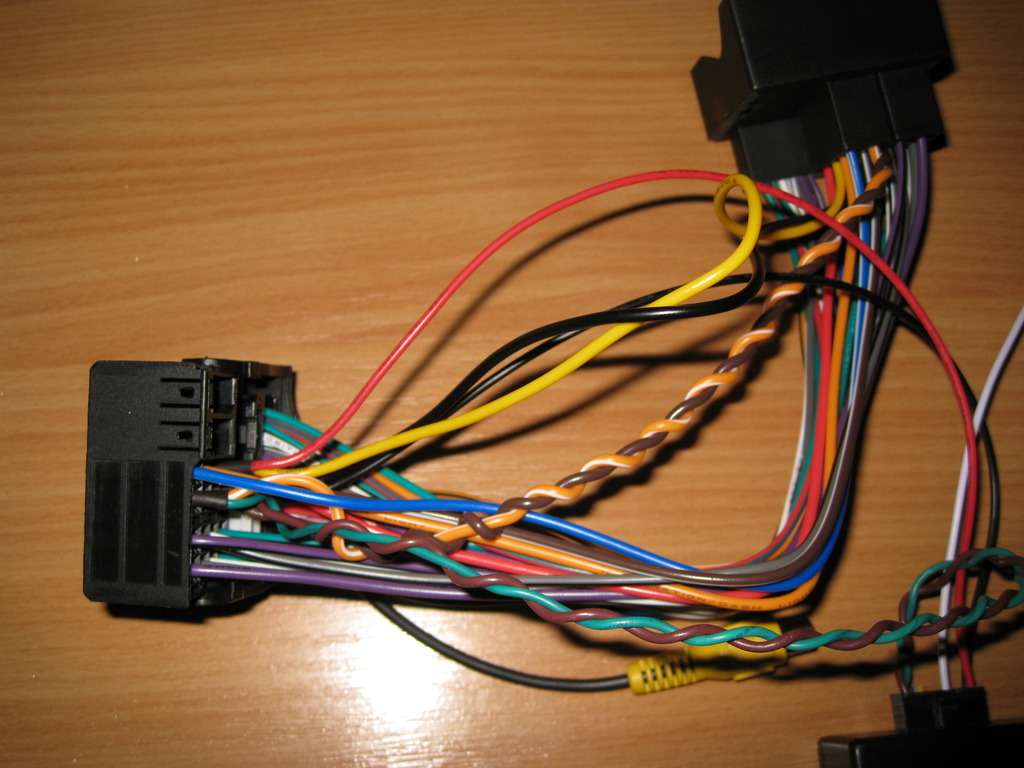 So that's the harness work done, just the final white cable to connect up once things are installed in the car - so much easier not having to do all this work in the car itself! 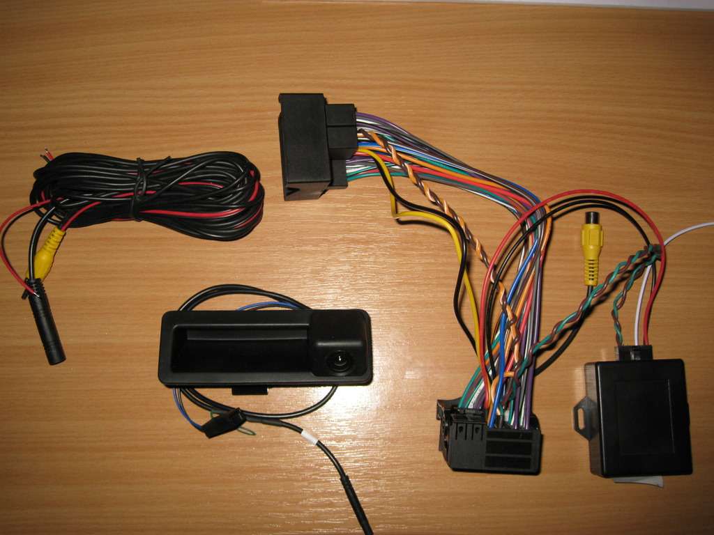 Ready to install this in the car this afternoon hopefully - I just have one question if someone could help please - in the picture below I've shown in arrows the connections that will go together when installed in the car, RCA to RCA, and white emulator wire to the red power wire coming out of the RCA cable which runs the length of the car. This still leaves one RED wire on the camera end - where on earth does this connect to? The other red power wire coming out of the RCA cable end obviously runs inside the main RCA cable down the length of the car and up into the camera, and the black cable at the camera end is connected to ground, but this leaves the red wire?? 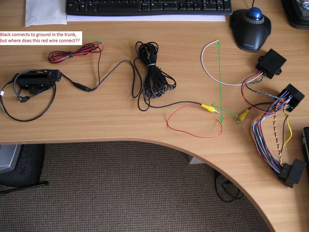 |
|
Appreciate
0
|
| 03-23-2015, 07:52 AM | #247 | |
|
Major
 
96
Rep 1,030
Posts
Drives: 335 E92 DCT
Join Date: Jun 2013
Location: Sydney, Australia
|
Quote:
__________________
Certified Australian
|
|
|
Appreciate
0
|
| 03-23-2015, 08:44 AM | #248 |
|
Private First Class
 
20
Rep 188
Posts |
Glad it's not me being stupid and missing something in the instructions then
 I'm wondering if it's simply an optional power source wire for the camera, if you choose not to power it form the white wire of the emulator? Like if someone wants to power it form the reverse light or something like that maybe? If that's the case we can just ignore it. I'm going to do the coding next and then plug in the harness at the front and give it a whirl and see what happens. Out of interest, did you use the grounding point above the rear wheel well for your camera earth? I'm wondering if it's simply an optional power source wire for the camera, if you choose not to power it form the white wire of the emulator? Like if someone wants to power it form the reverse light or something like that maybe? If that's the case we can just ignore it. I'm going to do the coding next and then plug in the harness at the front and give it a whirl and see what happens. Out of interest, did you use the grounding point above the rear wheel well for your camera earth? |
|
Appreciate
0
|
| 03-24-2015, 12:01 AM | #249 | |
|
Major
 
96
Rep 1,030
Posts
Drives: 335 E92 DCT
Join Date: Jun 2013
Location: Sydney, Australia
|
Quote:
From my end everything is hooked up as it should but this bloody RED wire is pissing me off. I've tried to ground it, to positive it NOTHING. I pretty much gave up because i kept pulling my car apart, i got sick of it FWIW I AM IN THE EXACT SITUATION AS YOU, EXACTLY!! I've codded my car already as well
__________________
Certified Australian
|
|
|
Appreciate
0
|
| 03-24-2015, 06:43 AM | #250 |
|
Private First Class
 
20
Rep 188
Posts |
Oh man, that must be frustrating as hell! Come on guys, this has got to be an easy one to answer for anyone who has installed this and got it to work - what did you did with this red wire???
|
|
Appreciate
0
|
| 03-26-2015, 09:33 AM | #252 |
|
Private First Class
 
20
Rep 188
Posts |
OK so I've had a response form the seller, which I'm pretty sure confirms my suspicions - this red wire in question is optional should you want to power the camera from the car's reverse light for example. You should not need to connect this if you are powering the camera from the emulator white wire (which connects to eh red wire at the RCA nav harness end). This is their response
Camera-------12V------ White The emulator's white line is 12V output, (You can use a multimeter to test the voltage of 12V) The white line need connecto to camera's red line 12v input . If the white line no output , You also can connect camera's red line to reversing light to get power. You can check photo of camera connection in attachment. Here is the picture they sent (which doesn't really clear anything up lol) 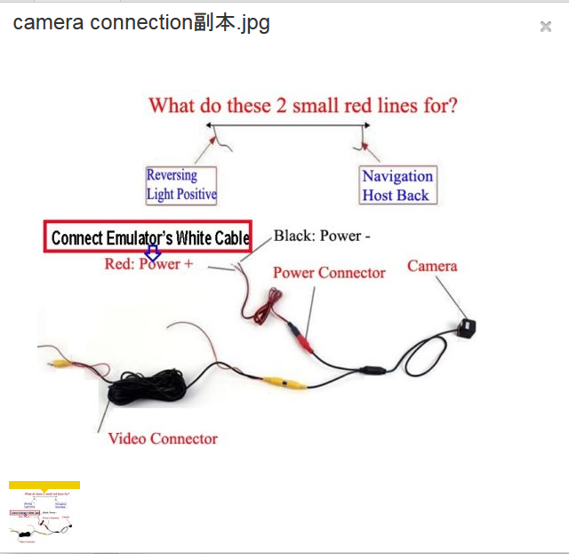 |
|
Appreciate
0
|
| 03-26-2015, 01:02 PM | #253 | |
|
Lieutenant Colonel
 243
Rep 1,857
Posts |
Quote:
 STEP 5: Pop out the navi and splice into 4 wires. The colors all match up. Attach the brown and green from the emulator to the brown and green on the navi harness (this is the CANBUS interface). Do the same the red and black (power wires). Lastly. the WHITE wire from the emulator is used to power the camera. So attach that to the cameras RED wire. You'll need to ground the camera at the trunk.
__________________
 |
|
|
Appreciate
0
|
| 03-26-2015, 02:09 PM | #254 |
|
Private First Class
 
20
Rep 188
Posts |
Thanks for the condescending attitude - I'm able to read. Perhaps you need to read what I posted a better
 Yes the red wire at the NAVI end of the long RCA cable attaches to the white emulator wire, that's obvious. What we are asking is what does the red wire coming out of the CAMERA end of the long RCA cable connect to? |
|
Appreciate
0
|
| 03-27-2015, 01:13 PM | #255 | |
|
Lieutenant Colonel
 243
Rep 1,857
Posts |
Quote:
__________________
 |
|
|
Appreciate
0
|
| 03-27-2015, 09:15 PM | #256 | |
|
Captain
    
73
Rep 629
Posts |
Quote:
Everything works fine as is. Hope that helps.
__________________
2009 335i E93 /// BSM /// Sport /// Premium /// /// 19" M pack 225 wheels /// M6 wheels winter set /// 35% Tint /// Gloss Black Grills /// PE Exhaust /// Lux H8 V3 /// Interior LEDs /// JB4-DCI /// Combox & CIC Retrofit /// M3 side skirts /// M3 front bumper ///
|
|
|
Appreciate
0
|
| 03-29-2015, 04:10 PM | #257 | |
|
Private First Class
 
20
Rep 188
Posts |
Quote:
 That's all I needed confirming, I don't know why this question was so difficult to answer!? I thought my picture with the annotations made the question very easy for anyone who had done this mod to answer, but never mind. That's all I needed confirming, I don't know why this question was so difficult to answer!? I thought my picture with the annotations made the question very easy for anyone who had done this mod to answer, but never mind. So to anyone else that gets stuck at this point - just ignore this red wire, tape it up, it is not needed. The only time you will need this red wire is if you choose not to power the camera from the emulators white wire, and decide to power it from the reverse light for example. This is the red wire I'm talking about (it's attached to the black wire which you fix to a grounding point) 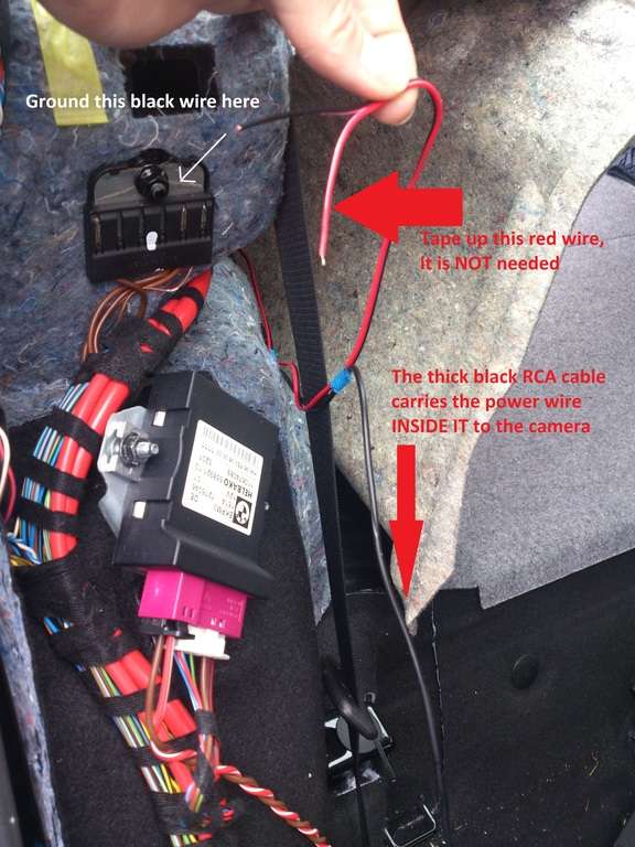 n8s 330xi - Might be worth just adding a note into your walkthrough about this red wire if you could please, just to help others that might get stuck at this point? ATTN - you should now be able to get this working if you've done the coding? After completing the necessary coding everything works perfectly  Old reverse screen 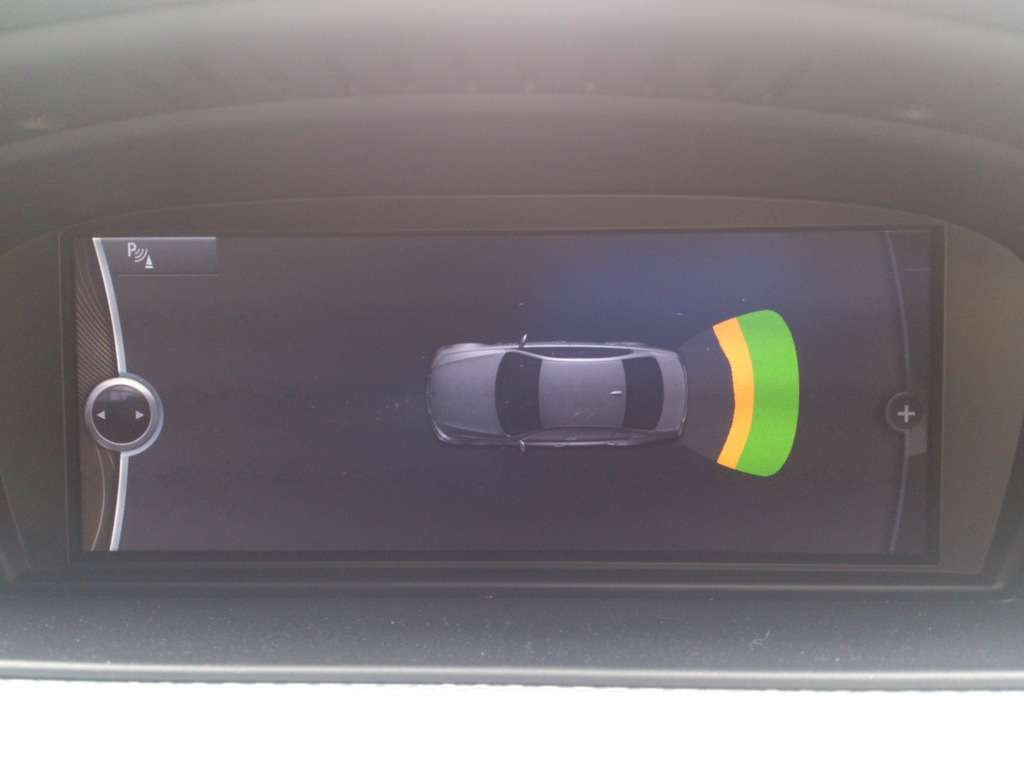 New reverse screen 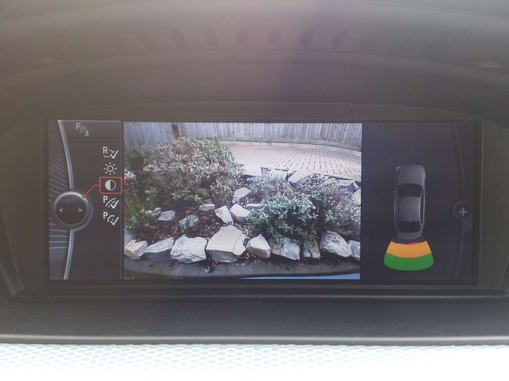 |
|
|
Appreciate
1
|
| 04-12-2015, 09:54 AM | #260 |
|
Private First Class
 
25
Rep 134
Posts |
Bump, can anyone confirm if this will work on the e82? I couldn't find info online on whether the e82 has the same connections as the e9x.
I'd like to order everything asap but want to confirm. Pleqse and thank you! |
|
Appreciate
0
|
| 04-13-2015, 10:03 AM | #261 | |
|
Private
 12
Rep 61
Posts |
Quote:
I think it's worth clarifying what that wire is - it's simply a jumper. It connects the power from the emulator to the power for the camera. I used it to power my camera. Unfortunately, the cabling varies a bit depending on the camera you purchase. Since I used 2 cameras, I ended up seeing both this wiring and the one that Rotary used for his. The camera setup you have is able to be powered by the white wire connection, via this red cable. That's how mine is wired.
__________________
2009 e90 335xi
 |
|
|
Appreciate
0
|
| 04-13-2015, 10:05 AM | #262 | |
|
Private
 12
Rep 61
Posts |
Quote:

__________________
2009 e90 335xi
 |
|
|
Appreciate
0
|
| 04-14-2015, 11:33 PM | #263 | ||
|
Private First Class
 
25
Rep 134
Posts |
Quote:
|
||
|
Appreciate
0
|
 |
| Bookmarks |
| Tags |
| reverse camera |
| Thread Tools | Search this Thread |
|
|