
|
|
 |
 |
 |

|
 |
BMW Garage | BMW Meets | Register | Today's Posts | Search |
 |

|
BMW 3-Series (E90 E92) Forum
>
ATC300 TC Actuator Wiring Diagram
|
 |
| 12-18-2023, 10:15 AM | #1 |
|
New Member
0
Rep 14
Posts |
ATC300 TC Actuator Wiring Diagram
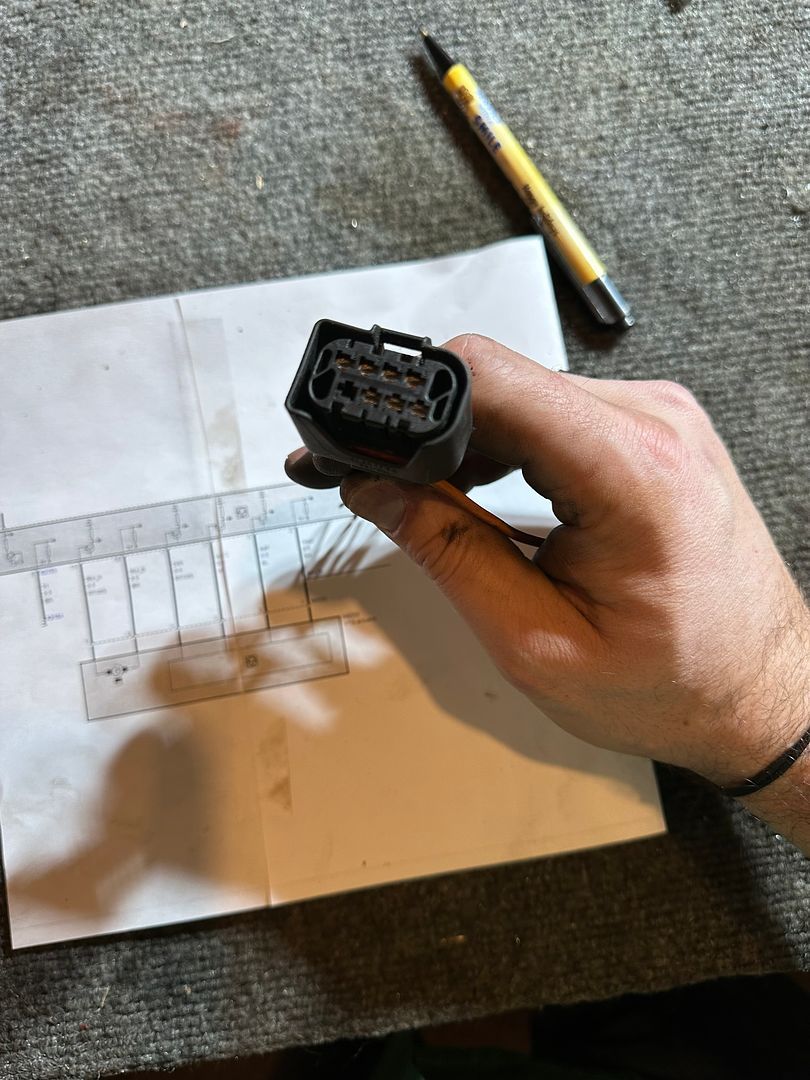
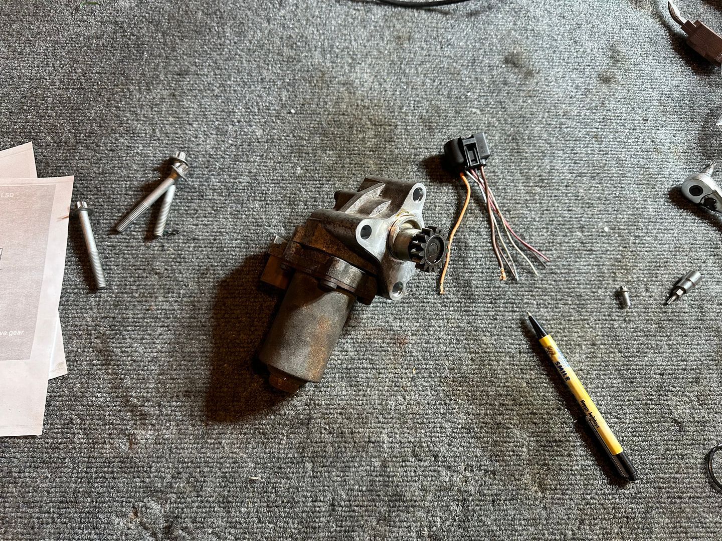
Hey everyone - I'm working on a project using an E90 6 spd with the ATC300 transfer case. Since this drivetrain isn't going to be controlled by the xdrive computer (and I don't see any aftermarket options) I am setting out to build a PIC-based transfer case controller. I could only find a wiring diagram from later X3/X4 but the wire colors aren't the same.
Does anyone have a copy of the diagram for the 7 pin connector as well as the 2 pin connector hanging off the end of the actuator? Thanks!    |
| 12-18-2023, 02:36 PM | #2 |
|
Captain
    662
Rep 786
Posts |
Nothing useful for your question....
I just hope that project X-drive e36 is going ice racing. Always thought a manual control for the T-case clutch would be really neat.
__________________
Sometimes a bolt is just a bolt.
|
|
Appreciate
0
|
| 12-18-2023, 04:11 PM | #3 |
|
New Member
0
Rep 14
Posts |
All of the above! I ultimately want to cage it to ARA rally spec should I ever decide to enter an event, but ultimately plan to build something akin to the raw early 2000ís STIís for fun gravel and two track driving. Planning M54 and turbo as well.
|
|
Appreciate
0
|
| 12-19-2023, 06:57 AM | #4 |
|
Lieutenant
   317
Rep 442
Posts
Drives: 2007 BMW 328xi E92 6mt swap
Join Date: Oct 2019
Location: New Jersey
|
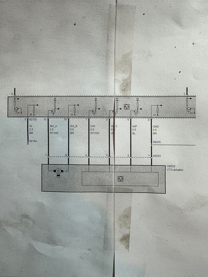
This is what I found for my car (E92 328xi, 09/06 production) and it seems like all other cars are similar, good luck.
 |
|
Appreciate
0
|
| 12-19-2023, 11:28 AM | #5 |
|
New Member
0
Rep 14
Posts |
|
|
Appreciate
0
|
| 12-20-2023, 03:43 PM | #6 |
|
New Member
0
Rep 14
Posts |
Doing some additional reading online and will characterize the circuits...nothing novel yet, but laying the groundwork to start fleshing out the system logic.
- IMP = Sensor output (hall sensor sensing rotation of the motor shaft...need to figure out pulses per motor rev/gear output rev/full sweep of clutch from 0 - 100%) - VCC = Sensor reference voltage... - TEMP = Temperature sensor in motor to limit control system aggression (per this xDrive link) - DIR = ??? One source says it's "transfer case motor voltage", but it's a small gauge wire so I assume this is some feedback from motor when powered. - SM_A = Motor Power 12V/PWM high side - SM_B = Motor Ground (Brown wire is also pretty well universally ground on any BMW I've touched, and I think circuit "31" in the control unit is ground) So here are a few open questions I'll be addressing via experimentation and documenting along the way: - Is the transfer case motor power supply (SM_A) truly PWM drive like a two wire throttle controller, or is 12V DC sufficient enough to drive it to a position? Will driving it at 12V regularly cause the actuator to overheat (hence the temp sensor)? - Is the servo motor controlled by an H-bridge (where SM_B can also go to 12V and SM_A to ground) to reverse motion on the motor? - At least by hand I am not able to back drive the motor gearbox...but the wiring diagram showing SM_B being a part of the "31" circuit and very clearly SM_A going to circuit "30", it looks like it is only polarized in one direction...so does the transfer case clutch mechanism have enough mechanical advantage to back drive the center diff back to "open"? If yes, this implies the TC actuator would need a steady voltage applied to keep the diff locked, which maybe makes more sense why there is a temp sensor in the actuator, but seems inefficient. - I've seen threads saying simply disconnecting the actuator results in 100% RWD/unlocking of the transfer case (among a bunch of other trouble lights)...is this because the car energizes the TC actuator to unlock when shutting down and disconnecting it while off keeps it open or is it because the actuator is allowed to be back driven...let's say we disconnect it immediately after 12V indexed it to 100% lock? - I might need to get an o-scope, but will attempt to measure current of the actuator under various conditions...will need to figure this out to adequately design the current sense circuitry for the PIC. I'll keep this thread up to date as things go along!! |
|
Appreciate
0
|
| 01-01-2024, 02:12 PM | #7 |
|
Private
 31
Rep 87
Posts |
Not sure but I don't think the motor backs out on its own where there's no voltage supplied by the VTG unit. I would say there's negative voltage given to back it out.
It will be difficult for you to really investigate this system without really driving the car with VTG unit connected to Can bus. The VTG unit has a calibration mode and I think this uses some kind of current sensing to establish start and stop points. When my transfer box was broken and the gear inside was loose the VTG was throwing a calibration error. |
|
Appreciate
0
|
| 02-10-2024, 01:22 AM | #8 |
|
New Member
0
Rep 14
Posts |
Follow along with my reverse engineering thread here:
https://www.e90post.com/forums/showthread.php?t=2071658 |
|
Appreciate
0
|
| 06-21-2024, 01:52 AM | #9 | |
|
Colonel
 1592
Rep 2,094
Posts |
Quote:
|
|
|
Appreciate
0
|
 |
| Bookmarks |
|
|