

|
|
 |
 |
 |

|
 |
BMW Garage | BMW Meets | Register | Today's Posts | Search |
 |

|
BMW 3-Series (E90 E92) Forum
>
DIY: N54 Engine Supply Coolant Pipe
|
 |
| 01-25-2014, 09:46 AM | #1 |
|
Master Gunner
77
Rep 435
Posts
Drives: 2008 335i Sport
Join Date: Aug 2013
Location: Sandy Eggo
|
I could not find any guides for replacing the Engine Supply Coolant Pump Pipe, aka Water Pipe, for the N54, nor was a procedure listed in the Bentley manual. TIS (2007) was very vague in describing the procedure, and the section directed to removal of the "primary catalytic converters" (i.e. downpipes) outlined steps to actually cut off the exhaust system. Hence my quest to document my trials and tribulations within this more detailed DIY undertaking.
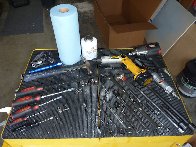
If you're leaking coolant at the connection of the water pipe to the engine block (bad gasket), or to the water pump (bad hose), you need this DIY. The gasket is sold individually, however, the rubber hose going to the water pump is not. It is attached firmly to the pipe with a thick clamp and is curved, although the possibility does exist to locate a same-sized hose with a similar bend in which a suitable section can be cut off and a regular hose clamp used to attach it to your existing pipe. However, keep in mind that the hose sits barely 2 inches away from the side and slightly above the front turbo and thus will be exposed to high heat. I seriously doubt a standard radiator hose will be able to withstand that situation for very long. 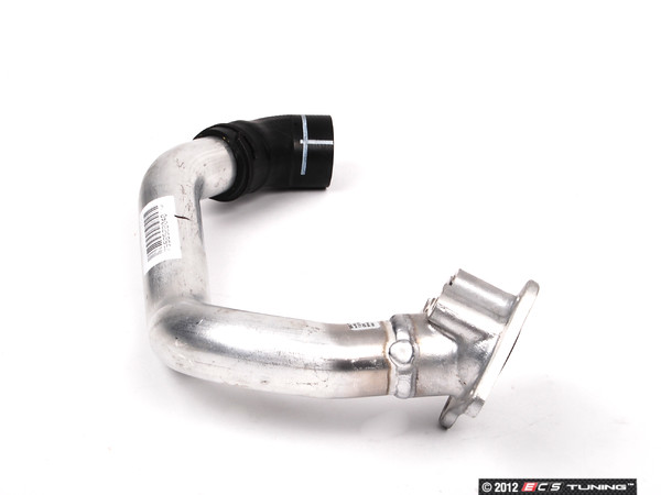 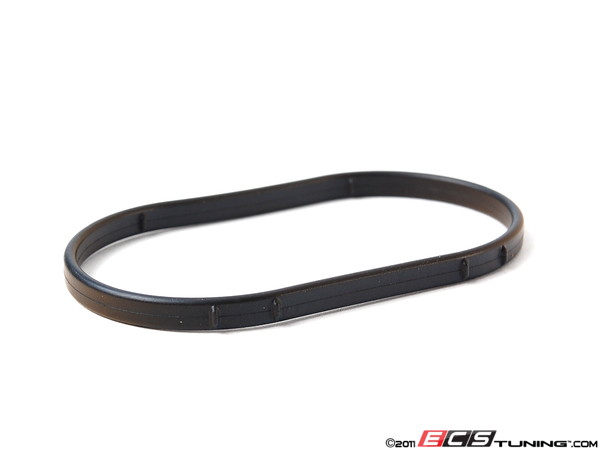 Be forewarned, this is not for the faint of heart as it involves removal of the downpipes plus working in confined spaces. I would imagine the vast majority would rather elect to pay someone to do the replacement but it probably won't be cheap. But for me, I gained valuable experience in preparation for when I do actually replace my DP's with an aftermarket catless set. As this involves draining the coolant, you could combine this procedure with other projects that involve coolant draining, such as water pump and thermostat replacement (which I already replaced two months earlier), or an OFHG R&R, which is what I did; I posted a DIY Addendum involving the Oil Filter Control Housing gasket. Tools and Materials Used
 Positioning the new water pipe to help visualize its orientation, locate key connection points, and plan a strategy for its removal. 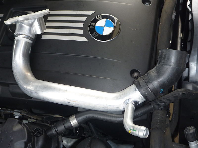 Engine Supply Coolant Pump Pipe Removal and Replacement Procedures Step 1: Raise vehicle, chock wheels if necessary, and remove front splash guard and splash guard brackets with 8mm socket. I only raised the front of the car as this allows sufficient room to maneuver the DP's in and out and access the exhaust clamp, but raising the back as well may help in reconnecting the exhaust to the downpipes if you do not have anyone assisting you. Step 2: Remove the down-pipes. Since there are numerous DP DIY guides available, I will refer you to a video one I utilized most: How To Install AR Design Downpipes, with the following suggestions:
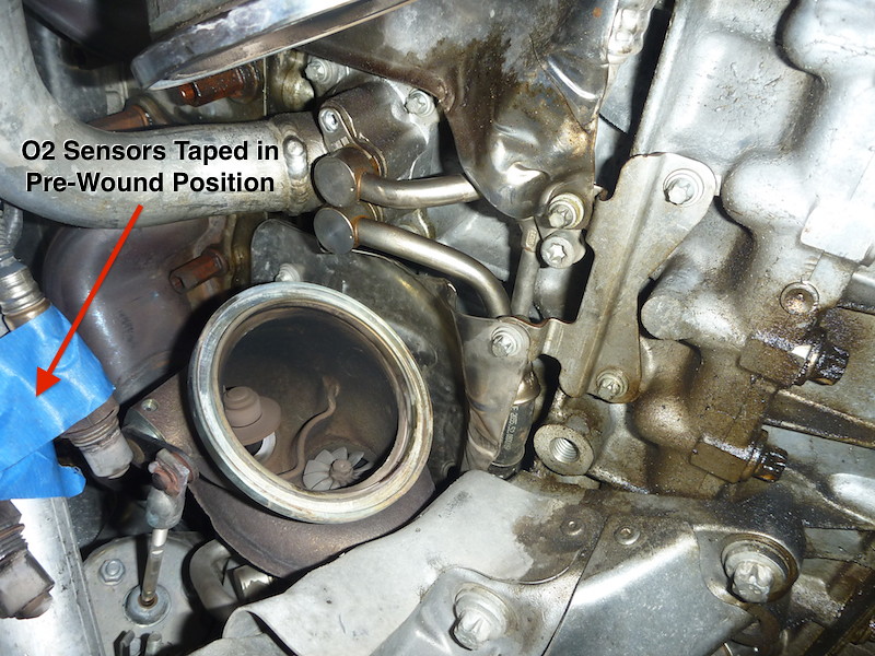 Step 3: Drain cooling system and remove thermostat-to-water pump hose to gain access to the water pipe hose. Remove the expansion tank cap, unplug water pump electrical connector, loosen the 6mm hose clamp on the U-shaped hose to the water pump and work the hose off slowly with a screwdriver to allow controlled coolant drainage into a catch pan. Once there is no more coolant draining out, loosen the hose clamp on the other end to the thermostat and work the hose completely off, draining any remaining coolant. Optionally, you can first remove the intercooler and drain most of the coolant through the radiator drain plug to lessen the amount of messy spillage and quicken the draining than just through the water pump alone; reinstall the drain plug when coolant stops draining. 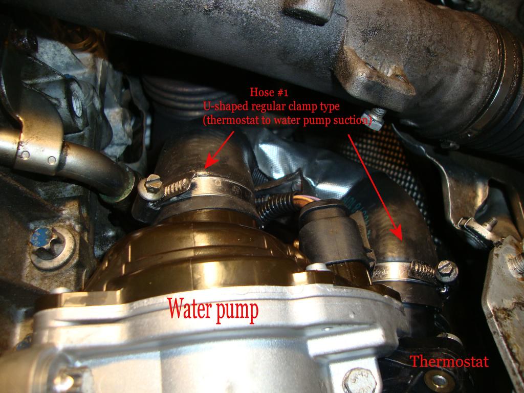 Step 4: Remove the coolant supply hold-down clamp T30 bolts and the lower heat shield E8 bolts; freeing the lower part of the heat shields will allow you to move the supply lines out of the way later. If you can wrest the supply lines out of the water pipe, then do so now. Mine were almost impossible to budge so I continued disassembly. The photo below shows the clamp bolts already removed: 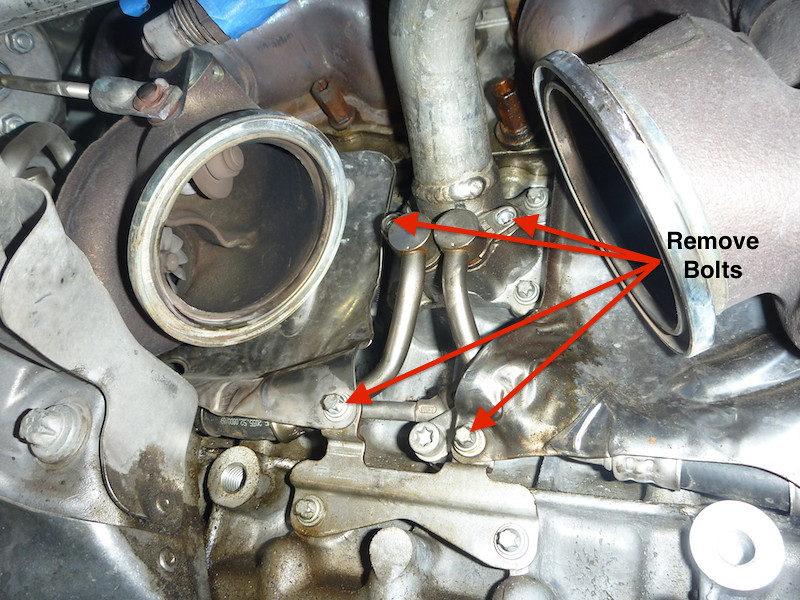 Step 5: Remove the 4 water pipe E8 flange bolts and separate the pipe from the block. This should allow more flexibility in removing the supply lines. Step 6: Wrangle the supply line fittings enough to gain clearance to insert a flat-blade screwdriver between the fittings and the water pipe mount, then alternating back and forth from the hold-down clamp to the fitting pry the supply lines free from the water pipe: do NOT mistakenly pry the groove in the fitting meant for the hold-down clamp. Have rags available to catch any spilling coolant. I've already installed the new water pipe when I took these photos for reference: 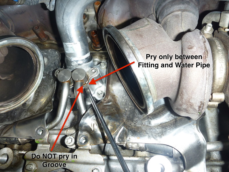 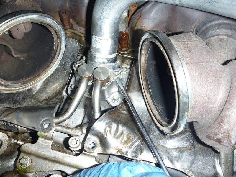 Step 7: Loosen the hose clamp on the hose connected to the water pump, then break the bond between the hose and water pump outlet using a screwdriver or hose removal tool. Step 8: Loosen the hose clamp on the coolant bypass hose connected to the branch tube and break the sealing bond. Due to it's location, it's too difficult to jab in screwdriver all around its circumference so a hose removal tool or a hook pick tool would be ideal. My hose clamp was clocked in such a way that made it impossible to get to without removing the expansion tank: 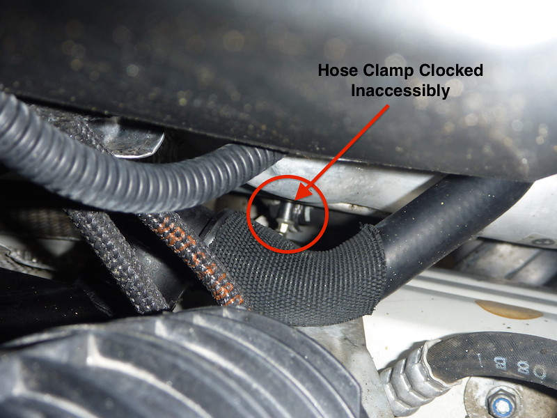 Even with the expansion tank removed, I couldn't get a socket nor screwdriver onto it because it was pointed directly towards the frame rail. I was forced into painstakingly small turns with an adjustable wrench. 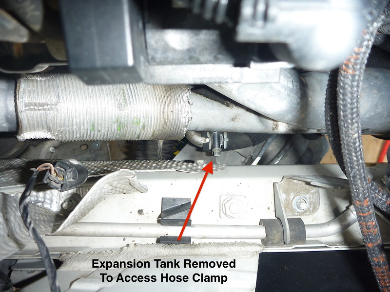 Step 9: Maneuver the water pipe to clear the heat shields, allowing you room to pull its hose off the water pump and the branch tube from the bypass hose. Guide the water pipe out from behind the crossmember. Step 10: Clean the block mounting pad surface of all residual gasket material with carb/brake cleaner while wearing leather gloves. The machined edges may have sharp residual aluminum shards; mine did and it sheared off a 3/8" long by 1/8" deep chunk of skin off my index finger; very painfully I might add. 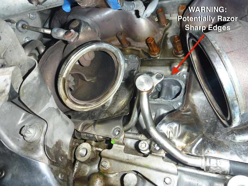 Here are comparison photos between the new water pipe and the old: 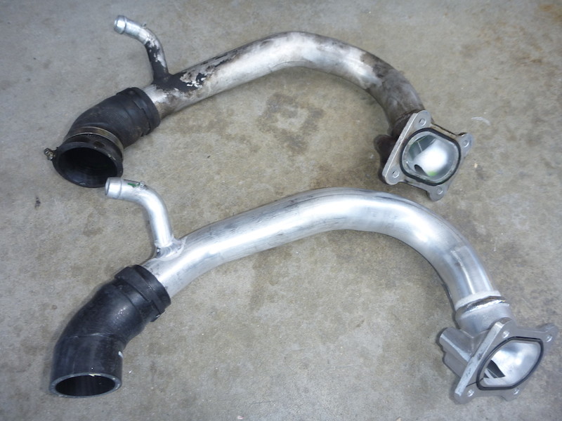 The old hose end was badly deformed:  But the source of the leak was a crack on the inner side of the hose, not visible when installed in the dark, cramped confines of the engine compartment: 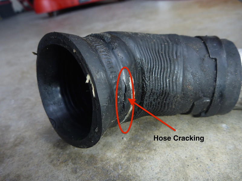 Step 11: Transfer the hose clamps to the new water pipe and ensure they are clocked correctly that they can be accessed for tightening while on the engine. I orientated the bypass hose clamp such that it would be accessible from below:  Step 12: Install water pipe from behind crossmember, fit bypass hose onto branch tube, water pipe hose to water pump, then finally seat water pipe flange between the heat shields and onto block mounting pad. Step 13: Install water pipe bolts and torque to 9 Nm. Install turbo coolant supply pipes and clamp bolts, tightening them to 20 Nm. Step 14: Fully seat the bypass hose lining up its groove with the alignment pin on the bypass tube, position the hose clamp between the white parallel lines on the hose and tighten with a 6mm socket to 3 Nm (my hands are specially calibrated for 3 Nm so I didn't need a torque wrench  ). ).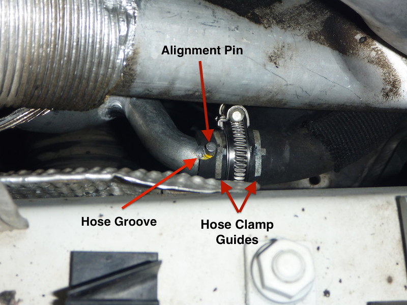 Step 15: Fully seat the water pipe hose to water pump, position the hose clamp within the guide lines and tighten to 3 Nm. Step 16: Reinstall the thermostat-to-water pump hose, again lining up the hose clamps between the guidelines and tighten to 3 Nm. Reattach water pump electrical connector. Step 17: Reinstall the expansion tank (if removed), fill cooling system with 50/50 mix of BMW Antifreeze and Distilled Water, perform coolant bleeding procedures, and check for leaks. Step 18: If the cooling system checks out, reinstall intercooler if removed, then reinstall DP's, with the following suggestions:
Step 19: Reinstall tie rod boot heat shield with T25 torx bit. Patience is required when carefully rethreading the self-tapping screws. Step 20: Pre-stage steering rack nuts on top of subframe, using the bolts to line them up with the holes. Mount the steering rack into subframe aligned to the holes, slowly insert bolts, shifting steering rack as necessary, and carefully thread bolts into nuts. Once both are properly threaded, fix the nuts with 16mm open-end wrench and torque the E12 studs to 50 Nm. If sway bar was unbolted, mount and torque the 13mm nuts to 21 Nm: if vehicle was raised onto jack stands with front suspension hanging, loosely attach nuts, wait until vehicle is back down and suspension has settled (short test drive) before torquing sway bar nuts. Once everything has been verified assembled with no "extra" parts remaining, start the car and check for any exhaust and coolant leaks. If all is good-to-go, install the splash guards and drive away with peace of mind and a big pat on the back for tackling a difficult project yourself! Last edited by Augster; 07-05-2017 at 01:14 PM.. Reason: To replaced image host links |
| 10-22-2021, 01:22 PM | #3 |
|
New Member

3
Rep 27
Posts
Drives: 335i Titanium / Black Dakota
Join Date: Dec 2009
Location: Atlanta
|
I'm going to second that, and hope I never have to do this!
On some car designs it would be simpler to pull the engine+trans as a unit and work on this deep of a repair externally |
|
Appreciate
0
|
| 11-27-2022, 07:39 AM | #5 |
|
New Member
3
Rep 26
Posts
Drives: 2009 328i
Join Date: Jul 2018
Location: Sugar Land, Texas
|
Thanks for this great DIY write up. Looks like I need to do this on my 2009 328I. Looks a lot easier but I still needed the Coolant Pipe bolt torques. Bentley is certainly missing any of this information.
|
|
Appreciate
0
|
| 08-04-2024, 12:20 PM | #6 |
|
Registered
0
Rep 1
Posts |
Hi.
I need to carry out this repair on my BMW 335i N54 engine and was wondering how long it would roughly take to do please. Got all the bits ready to start but was wondering on time frame to complete |
|
Appreciate
0
|
 |
| Bookmarks |
|
|